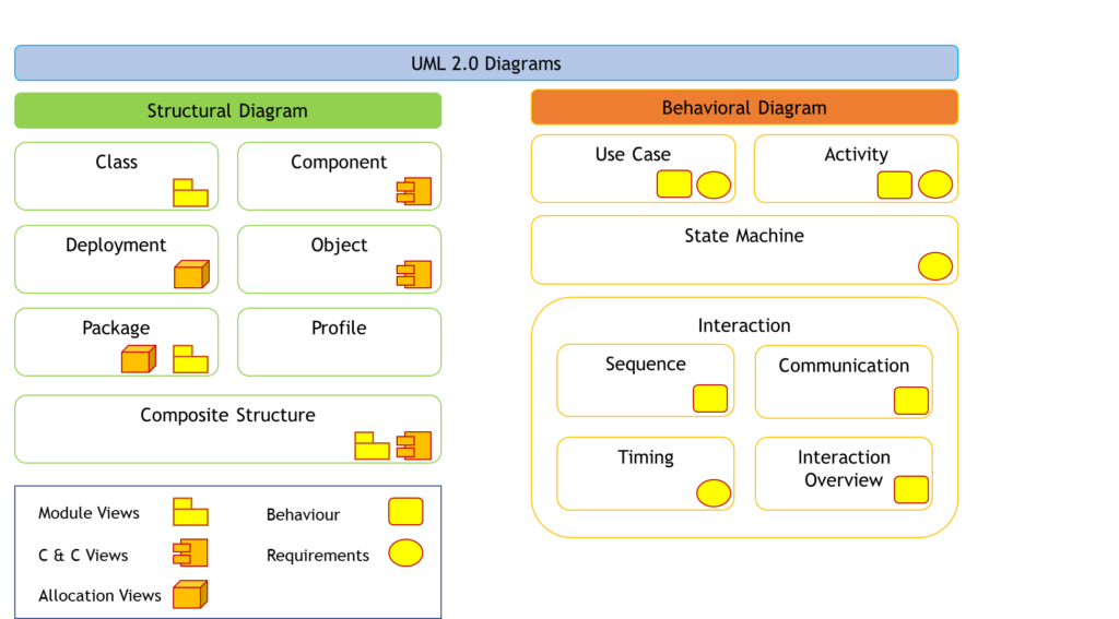
Structural Diagram
Structure diagrams define the static architecture of a model. They are used to model the ‘things’ that make up a model – the classes, objects, interfaces and physical components. In addition they are used to model the relationships and dependencies between elements
Class
- Class diagram shows the building blocks of any object-orientated system.
- Class diagrams depict the static view of the model or part of the model, describing what attributes and behavior it has rather that detailing the methods for achieving operations.
- Class diagrams are most useful to illustrate relationships between classes and interfaces.
- Generalizations, aggregations, and associations are all valuable in reflecting inheritance, composition or usage, and connections, respectively
Component
- Component Diagrams illustrate the pieces of software, controllers, etc. that will make up a system.
- Component diagram has a higher level of abstraction than a Class diagram
- Usually a component is implemented by one or more classes (or objects) at runtime.
- They are building blocks, such that eventually a component can encompass a large portion of a system.
Deployment
- Deployment Diagram models the run-time architecture of a system.
- It shows the configuration of the hardware elements (nodes) and shows how software elements and artifacts are mapped onto those nodes.
Object
- An object diagram may be considered a special case of a class diagram.
- Object diagrams use a subset of the elements of a class diagram in order to emphasize the relationship between instances of classes at some point in time.
- They are useful in understanding class diagrams.
- They don’t show anything architecturally different to class diagrams, but reflect multiplicity and roles.
Package
- Package Diagrams are used to reflect the organization of packages and their elements.
- These are used to divide the model into logical containers or ‘packages’ and describe the interactions between them at a high level
- Package diagrams are used to visualize namespaces when they are utilized to represent class elements.
- The most common uses for Package diagrams is to use them to organize Use-Case Diagrams and Class diagrams, although the use of Package Diagrams is not limited to these UML elements.
Profile
- Profile diagram, a kind of structural diagram in the Unified Modeling Language (UML), provides a generic extension mechanism for customizing UML models for particular domains and platforms.
- Extension mechanisms allow refining standard semantics in strictly additive manner, preventing them from contradicting standard semantics.
- Profiles are defined using stereotypes, tagged value definitions, and constraints which are applied to specific model elements, like Classes, Attributes, Operations, and Activities.
- A Profile is a collection of such extensions that collectively customize UML for a particular domain (e.g., aerospace, healthcare, financial) or platform (J2EE, .NET)
Composite Structure
- Composite structure diagram depicts the internal structure of structured classifiers by using parts, ports, and connectors.
- A structured classifier defines the implementation of a classifier and can include a class, a component, or a deployment node.
- It shows the configuration and relationship of parts that together perform the behavior of the containing classifier.
Behavioral Diagram
Behavior diagrams capture the varieties of interaction and instantaneous state within a model as it ‘executes’ over time.
Use Case
- The Use Case Model captures the requirements of a system.
- Use cases are a means of communicating with users and other stakeholders about what the system is intended to do.
Activity
- Activity diagram is used to display the sequence of activities.
- Activity Diagrams show the workflow from a start point to the finish point detailing the many decision paths that exist in the progression of events contained in the activity.
- They may be used to detail situations where parallel processing may occur in the execution of some activities.
- Activity Diagrams are useful for Business Modelling where they are used for detailing the processes involved in business activities.
State Machine
- A State Machine Diagram models the behavior of a single object, specifying the sequence of events that an object goes through during its lifetime in response to events
Sequence
- A sequence diagram is a form of interaction diagram which shows objects as lifelines running down the page and with their interactions over time represented as messages drawn as arrows from the source lifeline to the target lifeline.
- Sequence diagrams are good at showing which objects communicate with which other objects and what messages trigger those communications.
- Sequence diagrams are not intended for showing complex procedural logic
Communication
- A communication diagram, formerly called a collaboration diagram, is an interaction diagram that shows similar information to sequence diagrams but its primary focus is on object relationships.
- On communication diagrams, objects are shown with association connectors between them. Messages are added to the associations and show as short arrows pointing in the direction of the message flow. The sequence of messages is shown through a numbering scheme.
Timing
- Timing diagrams are used to display the change in state or value of one or more elements over time.
- It can also show the interaction between timed events and the time and duration constraints that govern them.
Interaction Overview
- An interaction overview diagram is a form of activity diagram in which the nodes represent interaction diagrams.
- Interaction diagrams can include sequence, communication, interaction overview and timing diagrams.
- Most of the notation for interaction overview diagrams is the same for activity diagrams. For example, initial, final, decision, merge, fork and join nodes are all the same. However, interaction overview diagrams introduce two new elements: interaction occurrences and interaction elements.