What is DFD
- Data flow diagrams (DFDs) reveal relationships between the various components in a system.
- DFDs are an important technique for modeling a system’s high-level detail by showing how input data is transformed to output results through a sequence of functional transformations.
- DFDs represent the following:
- External devices sending and receiving data
- Processes that change that data
- Data flows themselves
- Data storage locations
- DFDs consist of four basic components that illustrate how data flows in a system:
- entity (Source / Sink)
- process
- data store
- data flow.

Data Flow Diagram vs Flow Chart
- DFD is not a Flow Chart
- Flow Chart shows the flow of control
- DFD shows the flow of data
- The flowchart describes boxes that describe computations, decisions, interactions and loops
- It is important to keep in mind that data flow diagrams are not flowcharts and should not include control elements
Data Flow Diagram – Modelling

Context Diagram
- Shows the context into which the business process fits
- Shows the overall business process as just one process
- Shows all the outside entities that receive information from or contribute information to the system
Level 0 Diagram
- Shows all the processes that comprise the overall system
- Shows how information moves from and to each process
- Adds data stores
Level 1 Diagram
- Shows all the processes that comprise a single process on the level 0 diagram
- Shows how information moves from and to each of these processes
- Shows in more detail the content of higher level process
- Level 1 diagrams may not be needed for all level 0 processes
Level 2 Diagram
- Shows all processes that comprise a single process on the level 1 diagram
- Shows how information moves from and to each of these processes
- Level 2 diagrams may not be needed for all level 1 processes
- Correctly numbering each process helps the user understand where the process fits into the overall system
DFD Diagramming Rules
1. DFD Diagramming Rules – Process
- No process can have only input and outputs. Process must have both input and outputs.
- Process label must be verb phrase
2. DFD Diagramming Rules – Data Store
- Al flows from or to a data store must move through a process.
- Data store label must be noun phrase

3. DFD Diagramming Rules – Source / Sink
- Al flows from or to a data store must move through a process.
- Data store label must be noun phrase

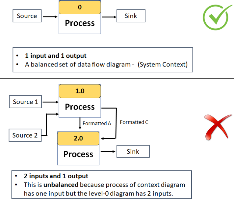
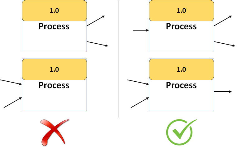
4. DFD Diagramming Rules – Balancing
- Balancing is the conservation of inputs and outputs to a DFD process when that process is decomposed to lower levels